Introduction
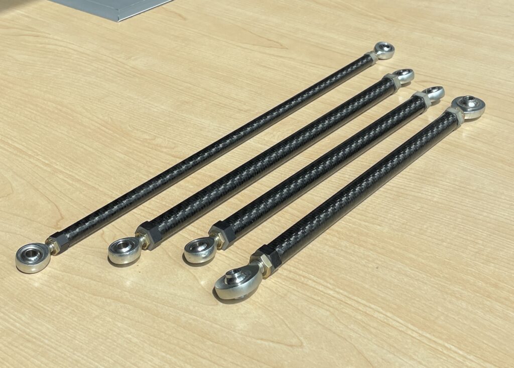
The most common material for FSAE suspension members is steel tubing. These systems can be made reasonably lightweight, but I saw the potential to reduce un-sprung mass even more by using carbon fiber suspension linkages; a first in TAMU’s 25 year FSAE history.
There are two parts to a linkage such as this: the tubing itself and the tube insert that allows attachment to the vehicle. It became quickly evident that the main point of concern when designing linkages like these is not the tubing or inserts themselves, but rather the adhesive bond which must be used to hold them together.
While there are hand calculations that can be performed to predict the strength of adhesive bonds, their estimates are very imprecise. For this reason, I needed to perform physical testing to validate my bonds before I could run these parts on the car.

For this testing, I tested 12 samples of each size linkage I planned to use. All these samples were bonded using Loctite EA20 HP adhesive with a .008″ bond gap.
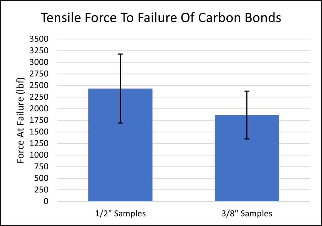
Using the lower bound of the 95% confidence interval shown in the plot, I now had load capacity values that I could use to estimate the FOS of these members. Electing to use these linkages for the push rods and tie rods of the car, the only tensile loading I needed to consider during normal operation occurred in the tie rods. Comparing the tensile capacity from this testing to my predicted load from my vector suspension force calculations gave a tensile FOS of 18 for the rear tie rods and 8 for the front tie rods.
To account for fatigue effects, I referenced a test done by Loctite to estimate how much reduction from initial strength I should expect with cyclic loading. Combining this with an estimate of the number of high G cornering events1 the links should see per mile from testing data, I generated a plot showing FOS as a function of testing miles.
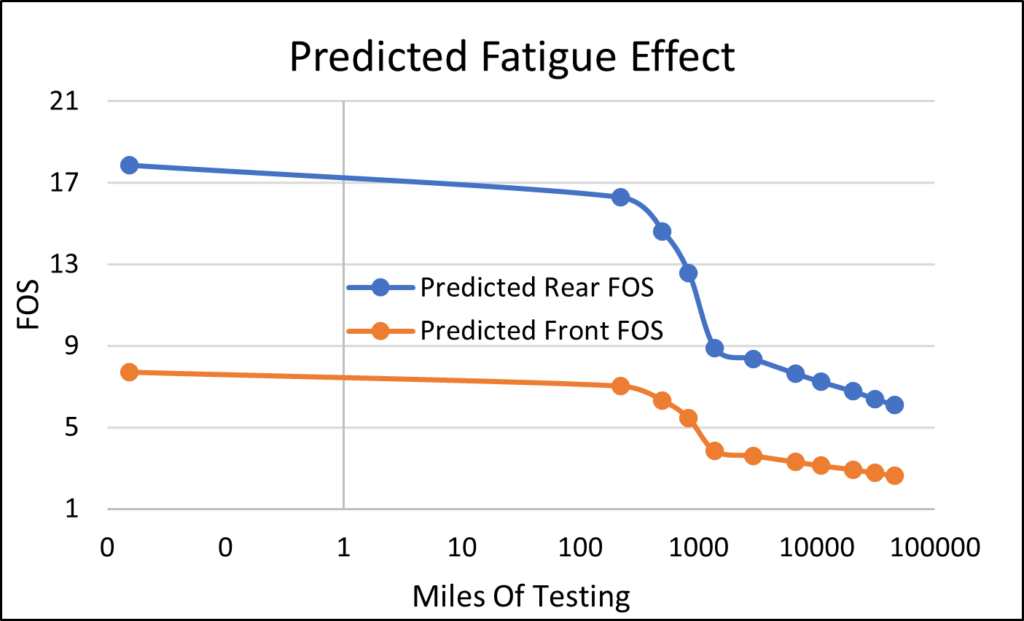
Based on this analysis, the lowest expected factor of safety after the planned 500 miles of testing was 6 for the front link and 15 for the rear link.
To estimate temperature effects, I used the strength vs temperature data on the EA20 HP data sheet to predict strength reduction.
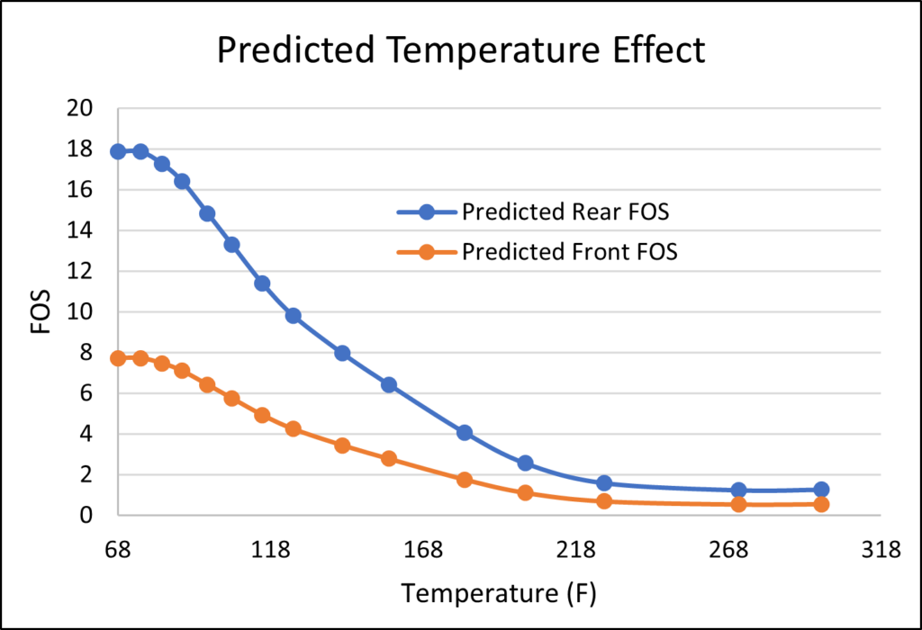
From on track testing, we found the maximum temperature of the links near the bond area to be approximately 120F. At this temperature, the FOS of the rear drops to 10 and the FOS of the front drops to 4. Considering a combined case of 500 miles of testing and a linkage at its max temperature, my worst case FOS was still 3.5 on the front toe rod.
Though there were many assumptions needed to complete this analysis under the tight time and budget restrictions of an FSAE project, I felt the resulting safety factors for the bonds were conservative enough to predict success on track.
Buckling Testing
As the pushrods only see compression with minimal tensile load in normal operation, pull out strength was not a major concern for these links. The more likely failure mode was tube buckling.
With the slenderness ratios of all the pushrods being greater than the critical value, the typical method to evaluate the buckling capacity is with Euler’s Formula. As carbon fiber is an anisotropic composite material, however, I needed to test the flexural rigidity of my rods to be able to use this formula. Knowing this rigidity and the length of each of the rods, this method gave me a rough idea of the pushrod buckling capacity as the length of these rods was modified throughout the kinematics design process.
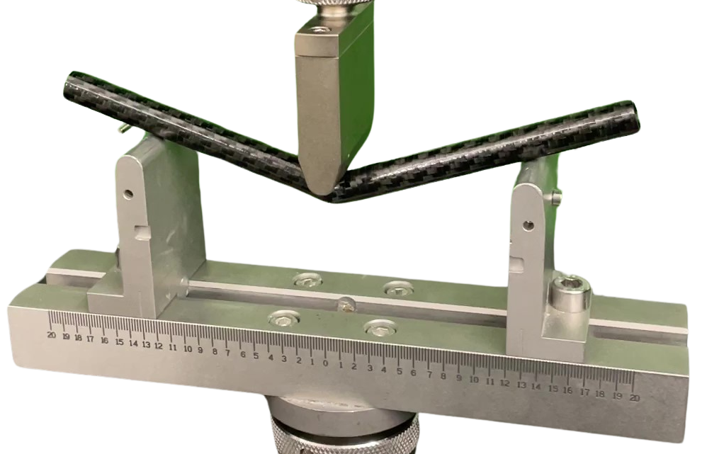
Near the end of the kinematics design process, the link with the greatest risk of buckling had an FOS of ~2. Given the low predictability of composites and the assumptions inherent in Euler Buckling Calculations, I believed this factor was too low to proceed without further inspection, so a buckling test was performed on this link.
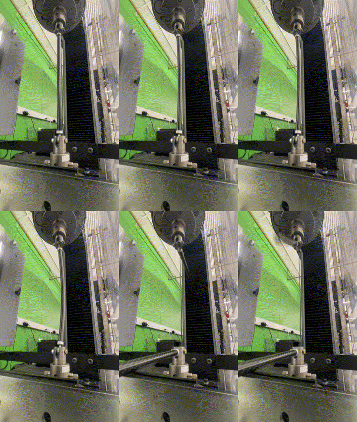
I was glad I challenged my calculations with this test, as the results showed a buckling load that was slightly lower than originally predicted. With these test results now projecting an FOS of 1.4, this design was slightly riskier that I was willing to accept. To combat this, I worked with the suspension actuation designer to make the linkage as short as possible, ultimately shortening it by from 16 inches to 13 inches. Performing another buckling test resulted in an FOS of 2.4 for this link, a notable improvement from the previous design.
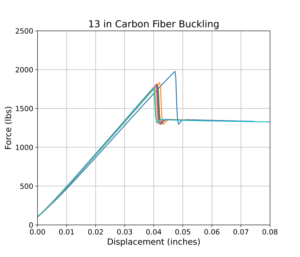
Another promising property of these carbon fiber links which you may have noticed from the testing videos was its ability to rebound after buckling. This can be seen in the testing data above, showing multiple buckling and rebound cycles for a single linkage. This means that even if a linkage were pushed to its buckling load for a brief moment on track, it could rebound to its original shape multiple times and continue functioning; so long as this load is not sustained for an extended time.
With the new FOS for the onset of buckling and the ability of the tubing to rebound from dynamic buckling, I felt sufficiently confident to install these components for full vehicle testing.
Weight Reduction
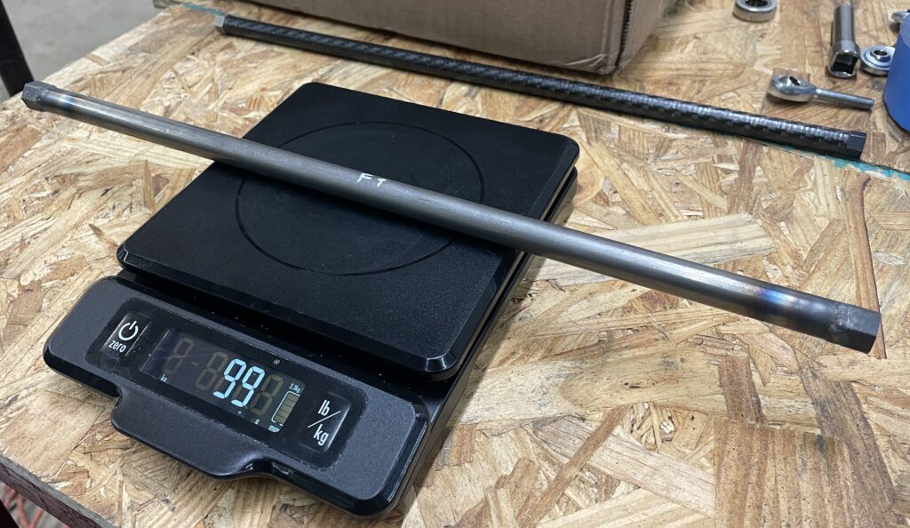
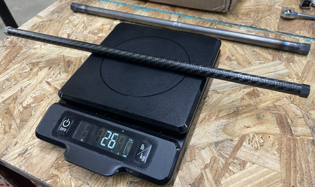
Comparing my carbon fiber linkages to a set of spare steel linkages made for the car, the carbon fiber were found to be as light as nearly a quarter the weight of a comparable steel link, and have a conservatively estimated stiffness to weight ratio almost double that of the steel.
On-Track Performance
I’m proud to share that these parts achieved this reduction in mass while still maintaining exceptional reliability, with no mechanical failures during full car testing or competition. This achievement allowed us to be the first TAMU FSAE car in three years to complete the endurance event, contributing to the team securing 5th place overall out of more than 100 teams at FSAE Michigan.
