Tesla used sheet metal guards to protect the vehicle lifter belts from being punctured by bolts. One of my later tasks was to improve these guards’ design and prepare documentation to make them for all the lifters.
Original Guard
Issue
Improvements
Needed to be removed to grease roller bearings
Accessibility holes added to the upper structure
Small hinge hardware was easily dropped or misplaced
less bolts used on hinges, increasing their size
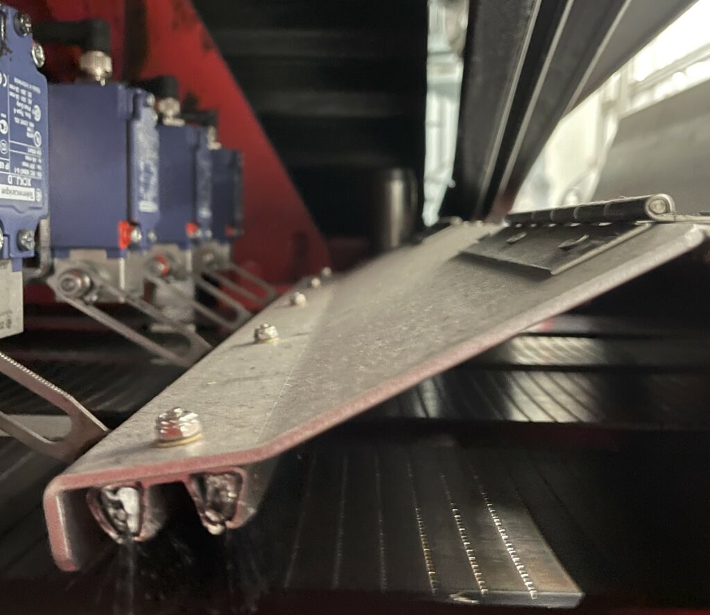
Sharp, downward leading edge caused belt wear hazard
Hemmed leading edge and increased front plate height to allow brushes to lay flat
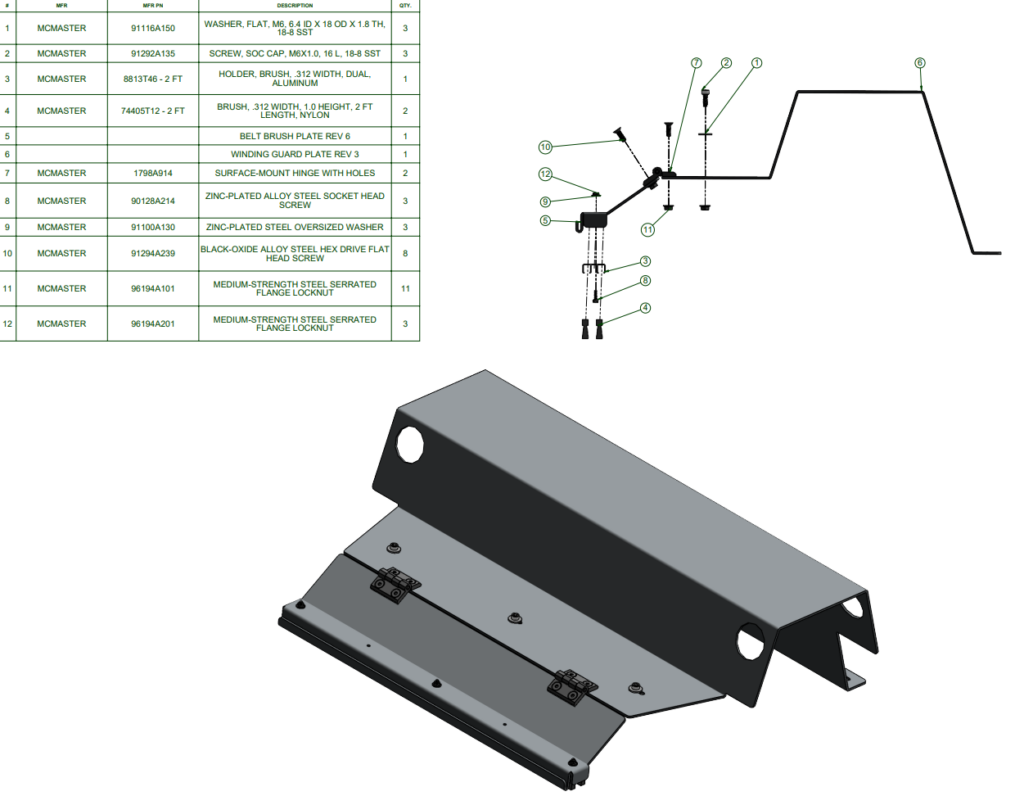
To implement these changes, I redesigned the part in CAD, found the necessary hardware to assemble the structure, documented everything using part drawings, and commissioned the fabrication of two sample guards from local fabricators.
Assembly Drawing
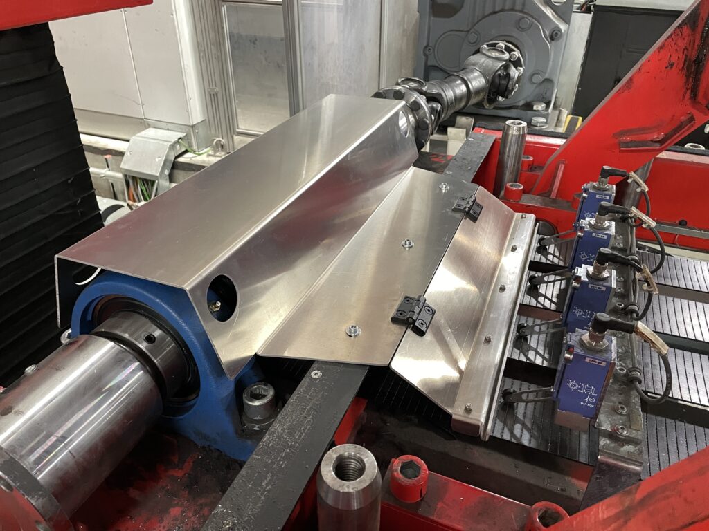
Fabricated and installed guard
With the guard installed, I needed to test it to ensure there were no clearance issues or possibilities of excess friction flipping the leading edge back. After running the lifter through three cycles under close inspection during a shutdown, the team felt confident deploying it for production.
Clearance Testing
Despite the small clearance in the front, necessary to block the tip of chamfered bolts, this iteration of the guard saw no issues during my time at Tesla. With the documentation I created for this part, my team was prepared to order these for every lifter.
During my time at Volcon, there was a need to improve the installation process of motors and swingarms on the Grunt motorcycles. To address this need, I took it upon myself to develop installation trolleys that would improve these processes.
Requirements
Carry a 40 lb motor 10 feet from the storage rack to the frame jig
Be compatible for part installation with Volcon’s existing frame jig
Eliminate any pinch hazard during the installation process
Decrease risk of frame damage during part installation
Brainstorming
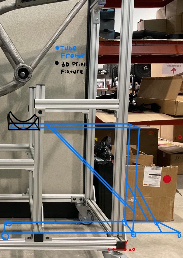
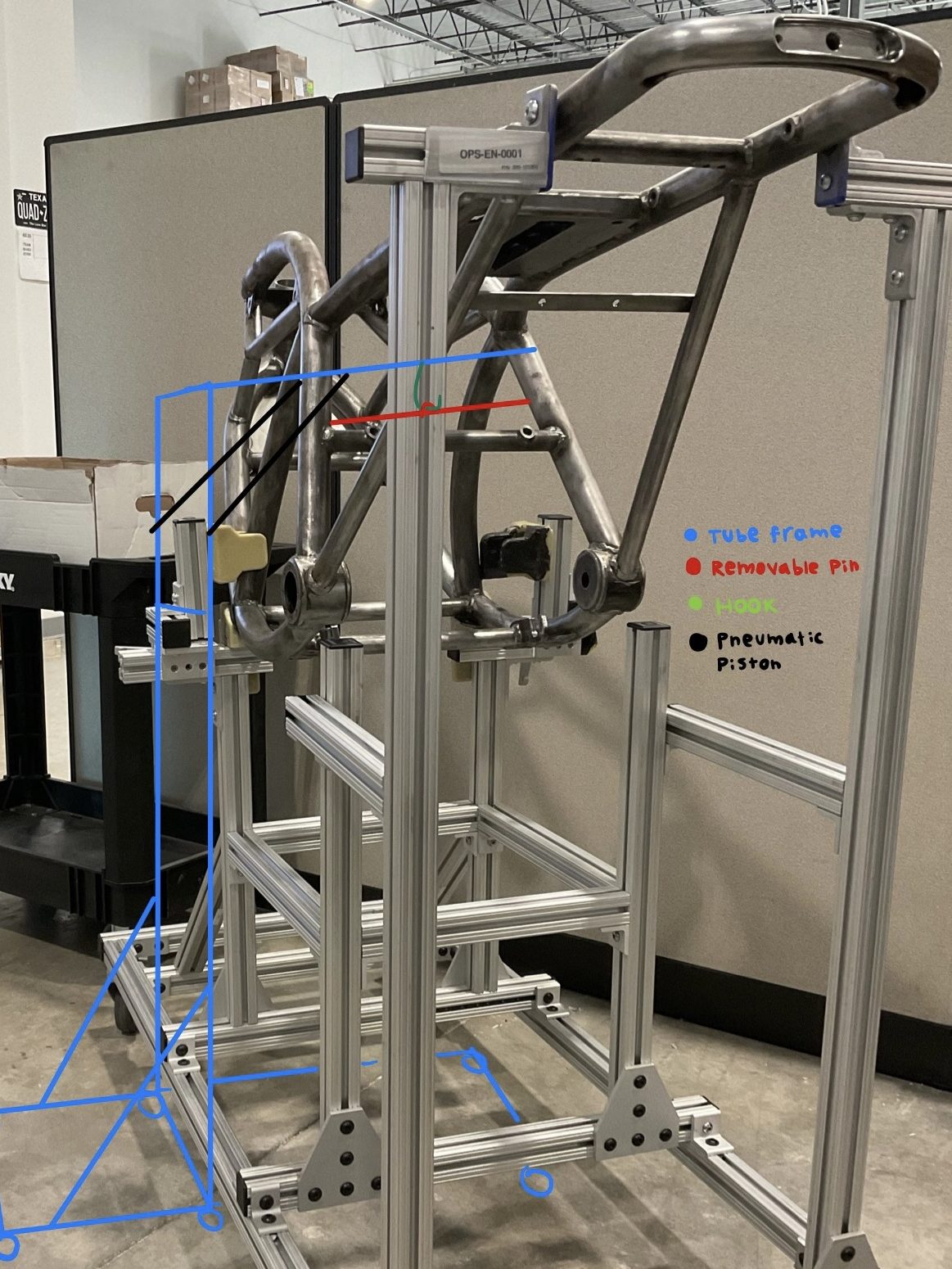
With the requirements identified, I did some brainstorming to come up with possible designs to fulfill them. Sketches of the two main concepts are shown below.
Rear-Install TrolleySide-Hoist Trolley
After some consultation with fellow production engineers, I decided to move forward with the rear-installation configuration because of its simplicity and cheapness, and favorable packaging.
Trolley Frame
I chose to use a Flexpipe tubing structure for the frame of the cart because it is cheap, easy to assemble, and allows for modification of the structure even after construction.
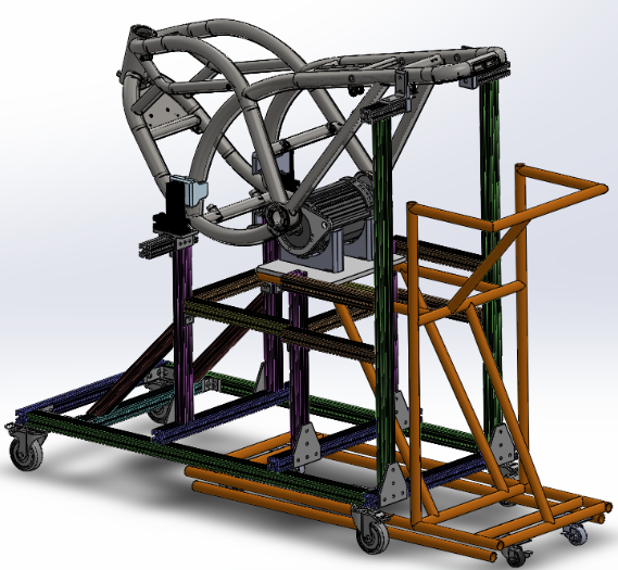
To model the frame, I used Solidworks Weldments to create a part within the context of the Grunt Frame Trolley assembly.
Solidworks Model of Trolley With Stiffened Frame
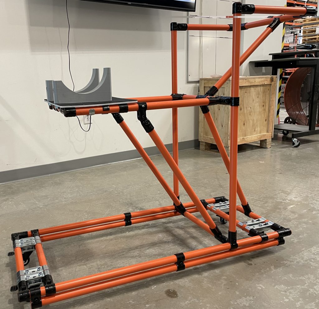
After constructing the frame, I noticed the platform would flex somewhat excessively when loaded with the motor. To fix this, I added a second member below the base to increase its flexural rigidity. From the following media, the change in deflection looks somewhat minor, but this stiffening made a significant effect on user confidence when loading the frame.
Initial designStiffened design
Fixture Design
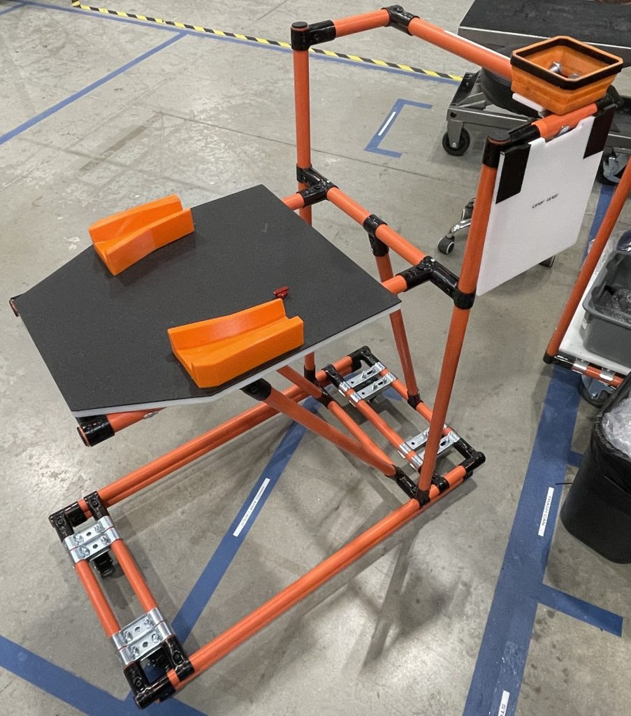
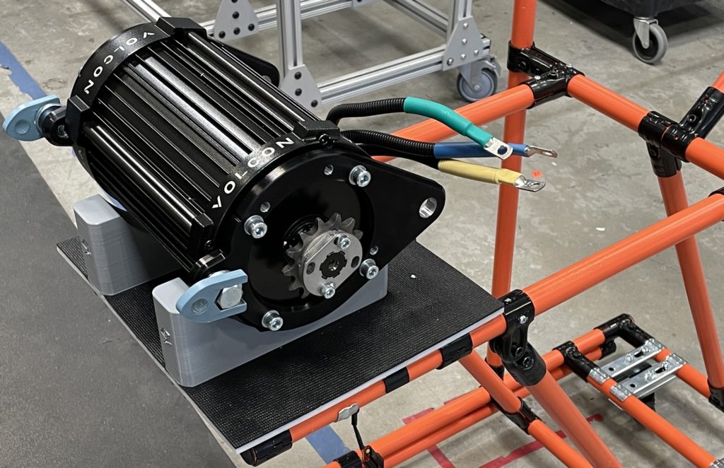
The fixture I designed was a two-piece half-circle cradle that fits the outer diameter of the motor. This design secures the motor as the trolley is positioned, but also allows for the motor to be rotated to its mounting brackets once in position.
The fixture was 3D printed from abs plastic, chosen for its strength and low-friction surface to allow the motor to be rotated. This fixture was then attached to the trolley base using threaded inserts.
Fixture Being Printed
Motor Washer Restraints
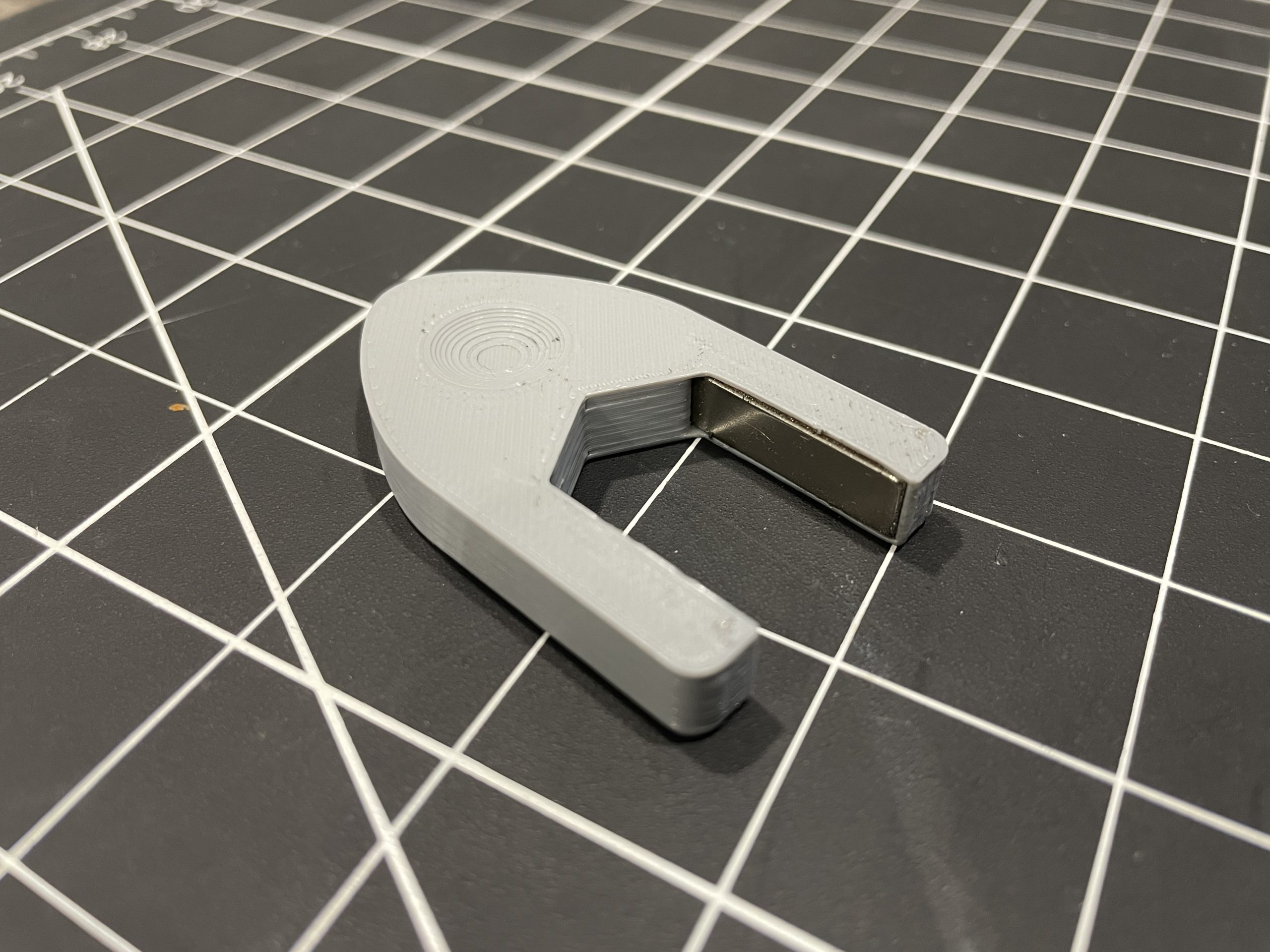
Another design that was implemented with this cart was that of a custom ‘washer restraint’. The idea for this device came about when observing the fact that associates would often have to hold the motor washers back during installation, presenting a possible pinch hazard.
To solve this, I designed a part that would go around the bolt with magnetic inserts, keeping the washers in place and alleviating the pinch hazard.
Once I tested the device and was satisfied with its function, I made more sets and updated the motor assembly process to have them pre-installed at this substation.
Swingarm Installation Fixture
With the motor installation cart finished, I proceeded to create a similar trolley with a modified fixture to hold the swingarm. This was created using a Solidworks cavity feature to fit the complicated geometry of the part
This fixture was printed with grippy and soft TPU and was likewise fastened with threaded inserts.
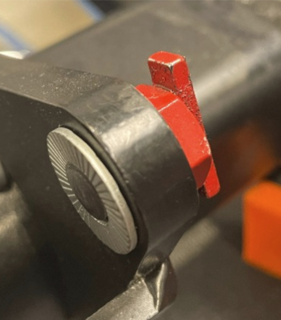
Swingarm Washer Restraint
I also developed a washer restraint for the swingarm cart. The basic design was a magnetized rod that would secure a washer around its edge. This restraint would be easily pushed out as the associate inserted a bolt into the hole.
Outcome
These carts were able to improve these operations by decreasing the risk of operator injury and NCM incidents, all while improving time efficiency by about 10%.
Learnings
The design process for these devices helped further develop my ability to come up with innovative solutions to unique problems.